Inductive measuring beams
It is produced a few types of inductive measuring beams marked with letters IH, IM, IL - (Inductive high, inductive medium , inductive light), in which with all the scales of MENSOR company are equipped.
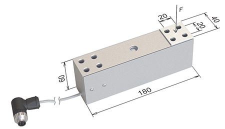
Fig. 1 Inductive measuring beam, ranges from 200 kg to 400 kg type IH2
Type IH2 beam has a special spring performance measurement, which is a variable cross-section to obtain a uniform stress distribution throughout the work area. Thus it has excellent metrological properties and can be charged with the applied forces which are not significant in the axis of the beam.
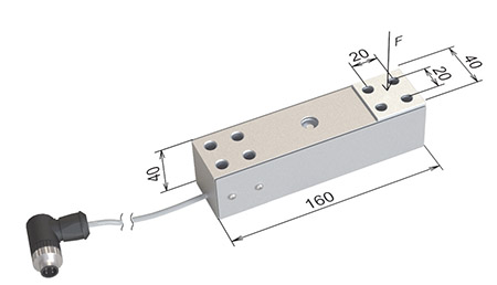
Fig. 2 Inductive measuring beam, ranges from 30kg to 300kg type IH
Beam type IH is most often used in class III electronic scales, for example in medical personal, animal weighing, storage, chair, bed, and others scales. In all inductive beams, there is the principle of measuring the total deflection of the beam as opposed to the strain gauge where we measure the deformation on the surface of the beam. This principle allows to simplify the construction of the measuring spring and achieve the requirements of metrological scales for class III. Hence IH beam is used in very different scales, they are made 160 mm and 180 mm of length.
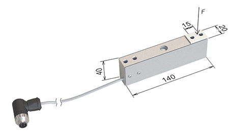
Fig. 3 Inductive measuring beam, ranges from 1.5 kg to 30 kg type IM1
Smaller forces and stresses for the load weight from 1.5 kg to 30 kg require a different beam geometry IM in relation to the above-described inductive beam type IH. Thickness of the beam type IH is 40 mm while inductive measuring beams IL and IM, have a width of 20 mm .
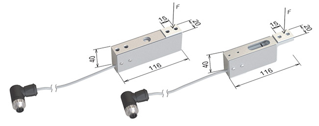
Fig. 4 Inductive measuring beam - ranges from 500g to 5 kg (on the left) and for ranges from 150g to 500g type IM2
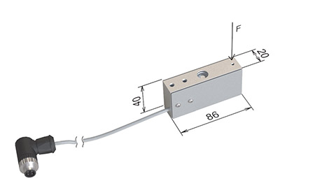
Fig. 5 Inductive measuring beam - ranges from 25 g to 50 g of type IL
Inductive measuring beam IM2 type differs from the length of the beam IL and the way of mounting pan. IM2 beam length is 116 and it has two holes for mounting M4 pan.
Inductive measuring beam IL has a length of 86 mm, it has the hole of 1,4 mm. In this case, the pan is round and can be easily removed, eg. for transport or for the purpose of cleaning.
Above described inductive measurement beams are characterized by:
- High mechanical resistance to overload - for small ranges up to 1000%
- High resistance to axial load hence large dimensions of pans.
- High accuracy as a result from lower than in strain gauge load cells stress - the resolution of 1mg
- The possibility of design the scales with small measuring ranges for example 0-25g
- Small sizes and high resistance to overload, significantly reduces the own weight of the scales
- Inductive beams are more resistant to side impact forces,
Inductive transducers
Inductive beams can be fitted with a measuring amplifier with processor compensating its metrological errors: hysteresis, creep, linearity, the effect of ambient temperature changes, etc. In this way, we have a range of transducers mass measuring, ranges from 25g to 400kg – similar to electronic scales with outputs: USB , RS232 or RS485. The transmitters can be built as shown in Figure 6 for measuring ranges from 30kg to 300kg or can be used without housing.
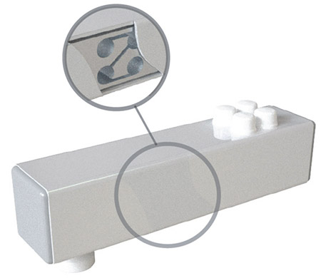
Fig. 6 Transducer of mass with the measuring beam type IH, shows the housing section of the beam
Fig. 6 shows the transducer mass of the measuring beam type IH housed in a sturdy powder-coated steel enclosure, made of square steel profile 50x50 mm, with 2 mm wall. At the end of the transducer Figure 6 we can see the adjustable leg, which in the waterproof version is located in the flexible membrane.
This design is intended for the construction of scales requiring the use of several transducers and for industrial applications, for example: measuring the weight of the suspended tank on three measuring modules. From the top there are four caps imposed on the M8 screws mounting beam to the base, below are the same four screws - this is a particularly strong and rigid connection of the beam to the housing.
Transmitter mass measurement of the beam: IH, IM1 and IM2 is used in electronic scales produce by MENSOR company with measuring ranges from 3kg to 300kg, which have a Certificate of EC type approval PL 06 003 Central Office of Measures. High reliability of the above. transducers made it possible to provide 5-year warranty period for these measuring units. In one profile on the side of 50mm made from steel can be mounted two inductive beams type IH, as in Figure 6. The length of such a measurement module Figure 7 can be from 0.5 m to 1.5 m.
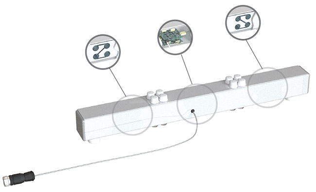
Fig. 7 The transmitter based on the two beams
As in the case of the transmitter of Fig. 6 adjustable feet can be located in a flexible membrane, which provides water resistance throughout the measuring module.
If you need to measure a concentrated force, for example measuring tensile strength within the ropes, you can use the converter shown in Fig. 8. This solution is similar to hook scales such as WM150P2A (H) - there is not here merely a display assembly and electronics plate is placed in a metal housing with the measuring beam.
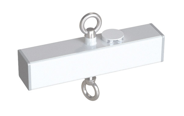
Fig. 8 Transducer for measuring the concentrated force
Examples of industrial applications
he above described inductive transducers can be used in various systems of continuous measurement of the mass (weighing systems). Each individual case often requires execution of a new project, completion of system components, installation and commissioning performance. Beam it will be described typical patterns of weighing systems available to build using inductive mass measurement transducers. To control the above systems can be applied the American Advantech software installed in Windows program in your computer, special software based on ARM processors or special drivers.
Prior to choose the measuring range of the transmitter and the determination of the control algorithm, tests should be done of the measurement object to determinie the size of the input and output, and to determine its dynamic properties.
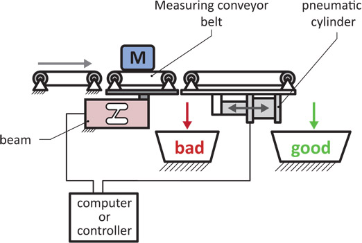
Fig. 9 Measurement of the mass in the technological process
Fig. 9 shows a diagram of measuring mass-produced items and the automatic selection of "good" and "bad" depending on the value of the measured mass. Pneumatic cylinder raises the receiving conveyor in the case of abnormal weighing mass item that falls into the trash "bad."
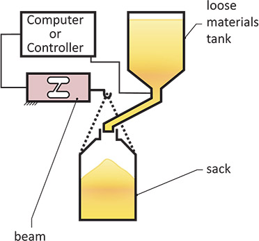
Fig. 10 Automatic batching of loose materials
Fig. 10 shows a schematic diagram of portioning loose weight into the bag hung on the con-verter mass. After the time of the bag filling, the signal of closing the valve outlet of the con-tainer is appeared
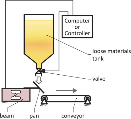
Fig. 11 Flow control of bulk materials
The falling material on the sloping pan fig. 11 exerts a vertical force component on the pan, which is measured by the transducer mass. The value of this force is proportional to the flow rate of material flowing from the tank. Reference to the control system is flow rate, which is compared with the value measured by the transmitter. In this way, you can set any flow rate, which, after setting maintains a constant value.
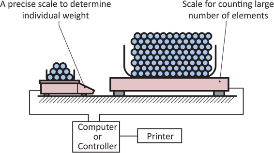
Fig. 13 The system of counting elements with the same mass using two scales: a small one with high accuracy and a bigger one with high measuring range
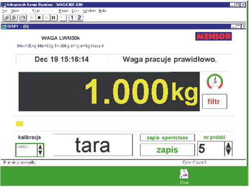
Fig. 13a. The counting scales systems made for Bertrand Faure; the first system is a small scale with the capacity of 2,5kg, a bigger one of 30 kg and the second system: a small scale with ca-pacity of 30kg, a big one of 2 tons.
The principle of two scales system is the accurate measurement of test batches of items on a small scale - the value of this mass is introduced into a computer program. While on the big scale is applied to the actual batch counting elements, whose number is indicated on the screen. By accurately designated trial batch of components is obtained an exact result of the count and there is no need to put a huge number of components on a small scale. The following system was built for industry by MENSOR company, a small scale had the range of 2,5kg and a big one of 30kg. Also the second system had a small scale with maximum capacity of 30kg and a big one 2 tons. With such a construction, it is possible to put on the small scale a few elements and for the big scale, a forklift basket mass used to put the counted pieces.
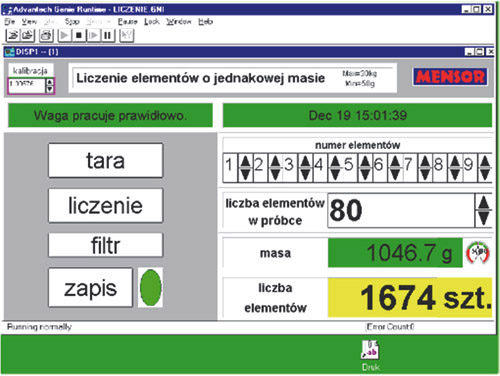
Fig. 13b The system of counting elements with the same mass using two scales – view of the display
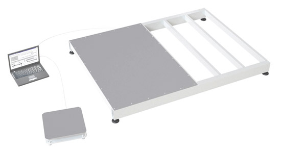
Fig. 13c The system of counting elements with the same mass using two scales – view of the scales
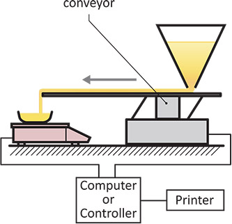
Fig. 15 Automatic batching of loose materials
Fig.15 shows a diagram of a precise portioning of loose materials using feeder vibratory, after reaching the required weight values measured by the scale, a vibratory feeder is turned off and it causes of stopping of the dosing process.
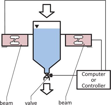
Fig. 16 Automatic weighing of liquids
Diagram of automatic weighing and portioning of fluid shows fig. 16. The tank with the liquid is still weighted by two transducers, whose output signals are introduced into the control system. Metering is made via cyclical reduction of the weight of the required value. The control valve is activated by a signal from the controller or a computer program.
Another example of industrial use is a central system for measuring of welding wire mass on production stands in the world's largest company Bucyrus America, which produce manufac-tures machines for the coal mining. The majority of manufacturing jobs in this company are welded machines which use the welding wire to meld their elements.
The control system has been designed for welding stands through continuous mass measure-ment of the welding wire which is located in a standard barrel. In this way it is controlled con-sumption of wire and the rhythm of work welders. From the graph of the mass of wire located in the barrel as a function of time, can be evaluated active period of time of welding . For the above measurements of mass, we developed a special design of scale for weighing barrels with welding wire figure 17.
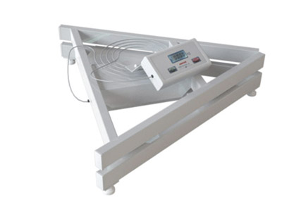
Fig. 17 The special scale for weighing welding wire in the barrel
Another example of a special design is the scale of 2 kg capacity designed for weighing glass mats (longer than 1 m) during the production system Fig.18. Weighing platform is made of alu-minum profiles here, also connected thanks to an aluminum frame with two spatial inductive measuring beams.
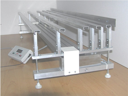
Fig. 18 The special scale for weighing glass mats
Another example is the special scale of 300kg capacity for weighing calves, made for an experi-mental breeding farm fig. 19.
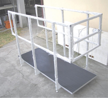
Fig. 19 Special scale made for experimental breeding farm for weighing calve
Cooperation with research institutes
MENSOR company has formal powers to conduct scientific research in the field of mass meas-urements. Our well equipped technological equipment, measuring devices and skilled staff al-low you to solve difficult research problems.
So far, cooperation with research institutes has been concerned a special design of research laboratory stands or the orders from institute to has been conduct of project research by MENSOR . Most institutes do not have a variety of technological devices and apparatus, which are necessary to build a special laboratory stands, particularly in the field of mass measure-ments. In these cases MENSOR company can solve such kind of problems. On the other hand, when executed by the MENSOR company it was necessary commission with institutes some parts of these researches. Thus, starting from the time of the chronology of company MENSOR company in the past 20 years has been working with the following institutes:
- Institute of Fluid Flow Machinery, Technical University of Lodz
- Institute of Bionics and Biomedical Engineering Polish Academy of Sciences
- Institute of Technology Precision and Electronic Devices, Faculty of Mechatronics, Warsaw University of Technology
- Department of Strength of Materials, Department of Mechanical Engineering Technical University of Lodz
- Medical University of Lublin
- Department of Materials Science and Engineering Warsaw University of Technology
- Industrial Institute of Electronics
- School of Information Technology
- Warsaw University of Technology Faculty of Electrical Engineering
- Department of Electronics and Information Technology Warsaw University of Technology
- School of Agriculture, Department of Food Science
- Faculty of Mechatronics, Military University of Technology
An example of the above. cooperation may be the laboratory stand for scientific study of fruit drying in a vacuum, made for the SGGW. The main measuring unit of the inductive measuring beam was placed in a vacuum chamber with trays connected to a system operated cyclically Figure 13. We have here an example of accurate measurement of weight in a vacuum chamber performed over long periods of time, during the evaporation of water from the dried fruit. An additional complicating factor in that measuring system was the heat supplied to the tested fruit during drying.
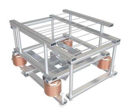
Fig. 20 The main measuring unit of the vacuum chamber to study the process of drying fruit, made for SGGW
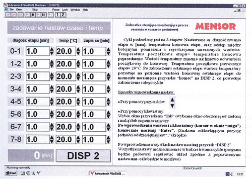
The control system measuring unit Figure 13 was designed using the computer program Ameri-can Advantech designed to automate various industrial processes. View of the monitor screen with the functions of control fruit drying process is shown in Fig 21
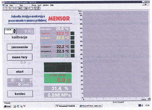
Fig. 21 View of the monitor screen of performing control functions in the process of drying fruit SGGW
Rys. 14a Widok ekranu monitora z funkcjami sterującymi proces suszenia owoców w SGGW
Another example of cooperation with the institutes may be a special pressure transducer with RS232 output to a computer is made for the Medical University of Lublin. Fig. 22 and 23 are shown in the monitor window from DISP 1 and DISP 2 The first of these digital displays are cali-brated in mmHg, kPa and mmH2O, there is a window with there44 graph of pressure variation as a function of time. Fig. 23 is visible from the window display from DISP 2 and chart the course of pressure changes on the left side you will see the slider to the polarization of the input signal for the measurement takes place in the 0-20 mmHg pressure changes.
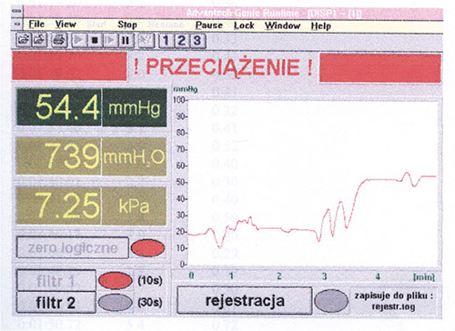
Fig. 22 Appearance of the monitor with the window DISP 1; three displays a graph of pressure and a graph of pressure changes
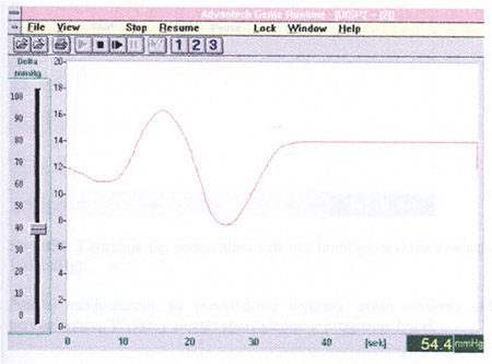
Fig. 23 Appearance of a window display DISP 2, the graph changes in pressure and the slider for the polarization of the input signal
An example of cooperation with the Technical University of Czestochowa is the special scale of 20g capacity to measure the mass loss of sample combusted at 1500oC. In this case application of the beam strain gauge is not possible and the use of a measurement system based on magne-to electric actuator is difficult. High temperature combustion required to hang the sample at the end of the rod placed in the furnace chamber. The other end of the rod combined with the inductive measuring beam Fig. 24 and the output signal shown in the display was visible to the left of the figure, and was introduced to the computer via the RS232 interface.
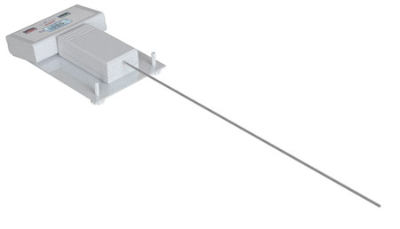
Fig. 24. Special scale for the Technical University of Czestochowa designed to study the combus-tion process at high temperatures.
An example of cooperation between the Department of Mechanical Engineering Technical Uni-versity of Lodz and MENSOR company was computer study of stress distribution in inductive measuring beam with a capacity of 400kg. These studies were performed in the framework of a research project SPAWAG conducted by the MENSOR company in cooperation with an Ameri-can Bucyrus company. Analysis of stress distribution in the inductive measuring beam fig. 25 permits to make optimization of metrological parameters and geometry of the beam.
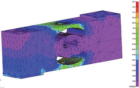
Fig. 25 Distribution of stress in inductive measuring beam with a capacity of 400kg
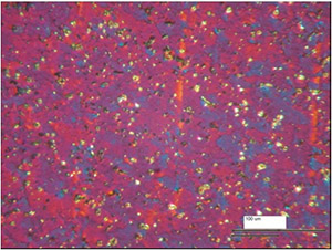
Another example of cooperation between the Department of Materials Science and Engineering of Warsaw University of Technology and the MENSOR company was to study the composition of metallography aluminum alloys (PA6) available on the European market. An interesting appli-cation of this research was that the percentage composition of aluminum alloy PA6 produced in Poland in Kety is the same as the corresponding alloy 2017A manufactured in Switzerland, how-ever, the elastic properties of the alloy made in Switzerland are much better, Fig.26.
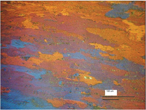
PA6 Kęty - Poland 2017A Switzerland
Fig. 26 Microstructure of aluminum alloy PA6 produced in Kęty and microstructure of the alloy of identical composition of metallographic 2017A manufactured in Switzerland (much better metrological parameters in the second case).
Above described metallographic studies carried out by the Department of Materials Science and Engineering of Warsaw University of Technology has been very helpful for the MENSOR com-pany when selecting material for inductive measuring beam
Contents
![]() About MENSOR company
About MENSOR company
![]() New inductive method for measure of mass
New inductive method for measure of mass
![]() Inductive measuring beams
Inductive measuring beams
![]() Medical scales
Medical scales
![]() Scales for weighing animals - Veterinary scales
Scales for weighing animals - Veterinary scales
![]() Electronic Platform and Storage Scales
Electronic Platform and Storage Scales
![]() Electronic table scales
Electronic table scales
![]() Electronic scales and parts counting systems
Electronic scales and parts counting systems
![]() Hook electronic scales
Hook electronic scales
![]() Electronic Precision Scales
Electronic Precision Scales
![]() Electronic Laboratory Scales
Electronic Laboratory Scales
![]() Electronic scales for production automation
Electronic scales for production automation
![]() Indication and dosing systems
Indication and dosing systems
![]() Weighing Modules
Weighing Modules