Indication and dosing systems
Application
An additional indication system limit indication of the weighing mass is designed for small and medium-sized companies producing larger series of the following: industrial, food, agricultural, fruit or confection companies of those products. A characteristic feature of the offered scales are easy to desire a weighing threshold weight or value, of calculated elements - hence the easy maintenance and low price.

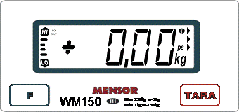
Figure 1 View of the front panel (for example, the scale of WM 150)
Signaling levels
On the left side of the display scale is placed a vertical line from the bottom completed with a sign "LO", from the top with a sign "HI". Turning on the alarm function of levels is indicated by a special mark on the scale display (left semicircle in the upper right corner of the display). When you turn on the signal function of levels and programming of both values, a sign "LO" is displayed for load values less than the lower threshold, a "HI" to a value greater than the upper threshold. For loads with values in the range <"LO", "HI"> shows the horizontal line (line item), which marks the location of the "LO" and "HI" represents the real difference between the values of the masses "LO", "HI" and measured value. This function works correctly in the normal weight. The values of "LO" and "HI" should be positive. Weight can be optionally equipped with a horn to the signal to indicate the range <"LO", "HI">. Also available as an option is to equip the weight in two independent relay outputs shorted and hinged respectively at the crossing levels, "LO" and "HI". (See additional description below).
Dosage control
This funtion is designed to turn on the solenoid valves, feeders, conveyors, etc., depending on the indication of weight, which enables precise (by weight) weighing systems of various substances such as powders or liquids. In order to increase the speed and precision of dosing can be used with two outputs of the scale to include e.g. two valves with different flow velocities. Enabling the alarm level is indicated by a special mark on the weight display (right semicircle in the upper right corner of the display).
There are two indicators of "LO" and "HI" on the display of the scale as shown on Figure 1 There are also introducer two outputs of two systems - releys (see below), whose short/opening is signalld by the inclusion of indicators as "LO" and "HI".
Description of relay Output from relay system


Additional relay outputs from the system of scale can be used for scale control via external devices such as signal crossing.
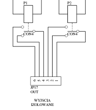
desired levels or dosage control. In the system - on the electronic display board (WAGA_PIC-05b) are 2 relays P1 and P2, containing or-off pins connected to the terminals on the PCB connector labeled as "OUT". The relays are switched accordingly after crossing the value of "LO" and "HI".
Output parameters of relays:
|
|
Nominal / Maximum switching voltage AC |
120 V |
Minimum switching voltage |
5 V |
Nominal current load in category AC1 |
3 A / 120 V AC |
Nominal current load in category DC1 |
3 A / 24 V DC |
Constant current load of contact system |
3 A |
Optional connector "OUT" may be connected with the connector 9 pin D-Sub, mounted in a casing or other suitable display for your application. Accordingly 1-2-3 and 4-5-6 exit are connected to pins 1-2-3 and 4-5-6 D-Sub connector.
Contents
![]() About MENSOR company
About MENSOR company
![]() New inductive method for measure of mass
New inductive method for measure of mass
![]() Medical scales
Medical scales
![]() Scales for weighing animals - Veterinary scales
Scales for weighing animals - Veterinary scales
![]() Electronic Platform and Storage Scales
Electronic Platform and Storage Scales
![]() Electronic table scales
Electronic table scales
![]() Electronic scales and parts counting systems
Electronic scales and parts counting systems
![]() Hook electronic scales
Hook electronic scales
![]() Electronic Precision Scales
Electronic Precision Scales
![]() Electronic Laboratory Scales
Electronic Laboratory Scales
![]() Electronic scales for production automation
Electronic scales for production automation
![]() Indication and dosing systems
Indication and dosing systems
![]() Weighing Modules
Weighing Modules