New inductive method for measure of mass
All electronic scales of MENSOR company based on a new inductive method of measuring mass and inductive load cells of Polish production - we do not import from China strain gauge load cells. The main advantage of method regarding strange gauge electronic scales are as follow:
- high mechanical resistance to overload - for small measurement ranges up to 1000% - possible large sizes of pan.
- high accuracy resulting than in the strain gauge transducers - resolution of the smalles inductive transducer is 1mg
- small size and high resistance to overload of the inductive measuring beams
- many times less own weight than the analogous scales equipped in weighing electromagnet system
- inductive beam is many times more resistant to side impact than the strain gauge beams
These advantages have been verified
- as a result of fifteen years of production of inductive scales on Polish and German market
- by the Central Office of Weights and Measures Certificate of EC type-approval No PN 06 003
- by Polish Centre for Testing and Certification CE Certificate No. MD - 220/1/2009
 by the users - Consumer Laurel Brown 2005
- inductive measurement system has been nominated in the competition of the Polish Product of the Future 1998 (in the category "Product of the future")
Research on the Inductive method of measuring mas were co-financed by EU funds within the three national research projects and is currently continuing in an international project EUROSTARS E! 4637 - EXCALE.
Theoretical basis of inductive method for measure of mass (pdf ver.![]() )
)
|
METROLOGY AND MEASUREMENT SYSTEMSIndex 330930, ISSN 0860-8229www.metrology.pg.gda.pl |
|
INDUCTIVE MEASURING LOAD CELL |
||
Janusz Lewandowski
MENSOR |
||
Abstract |
||
1. Introduction
Strain gauge load cells are commonly used for designing electronic scales and weighting modules. Mass production of these elements (Hottinger, Flintec, Mettler, Vishay, Sartorius) has improved its high technological level [1, 2] and caused low cost production – in such a situation working out the new solutions is extremely difficult. Looking for a new principle of work transmitter of mass and applying new physical phenomena, seems to be the only right way.
Strain gauge load cell consists of two elements: a springy beam, made usually from aluminum alloy or stainless steel and strain gauges sensors [7, 8, 9]. The idea of the spring beam as a measuring element is right, because it is stable, repeatable, resistant to over loaded mechanical forces. But there are some doubts about using foil strain gauge of sensors which are bonding on the beam for measuring of strain on its surface.
The strain gauge sensor is not resistant to over loaded outside forces, because it is connected with the beam by glue, it is put also to compression and tension during normal work [7]. The film of glue between the beam and strain gauge sensor has influence on static characteristics of electronic scales, especially for small ranges of mass measurement. As a result of this, value of errors caused by glue for ranges smaller than 0-200g is so significant that it is impossible to use here the strain gauge load cells - in practice below 0-2kg range. The electronic scales with above mentioned measuring ranges are designed thanks to magneto electronic systems.
Good elasticity properties of aluminum alloy and stainless steel permit designing transmitters of mass with high accuracy. As a results, the beam made from aluminum alloy is a good measuring element when we measure its displacement x as a function of the force:
where: F - measuring force (and mass), x – displacement at the end of the beam.
Using strain gauge for measuring of x displacement is not a good method, because the strain gauge measures strain the surface of the beam but not the whole displacement of its end. Considering above described problems, in our method of mass measurement, has been applied aluminum alloy for making the beam, but instead of strain gauge we use inductive sensor of displacement [3, 5, 6]. This sensor is a commonly known element and it is used very often for measuring small displacement with high resolution.
The above described principle is very easy, but in practice there are a lot of designing and technological problems which are the subject of this work. The main problem concerns influence of ambient temperature on the coil of inductive sensor of displacement which in this case works as a resistance temperature sensor. Similarly, the ambient temperature changes the Young module of aluminum alloy and elasticity of the beam.
The next important problem is a distribution of electromagnetic field around the inductive sensor which differently penetrates through air cracks and differently through aluminum alloy generates the vortex current. Above described electromagnetic field can be disturbed by metal element for example when we put the mass made from stainless steel. on the pan of electronic scale.
Achieved high resolution of inductive sensor displacement and its linear characteristics are a difficult design problem. Hence application of commercial inductive sensors is here impossible.
The main technological problem of inductive measuring beam concerns finding proper places of the holes and the canals inside the beam – it is necessary to choose optimal processing machine cutting and heat treatment processing of aluminum alloy.
The solution to the above described problems is the subject of this work which has been done for the last twenty years by research team from MENSOR company which cooperate with other institutes of technology. It is important that the results of this research work were applied in the production of electronic scales [4], tested by customers and the Main Measuring Office according to the European standards. This research and production process were repeated a few times to achieve maximum technological level of inductive measuring load cell – without connecting the production process with research, achieved results wouldn’t be possible.
2. State measuring system of mass
In the technique of measuring mass system there are generally two different measuring systems. The first one uses equilibrium system of forces with electromagnetic servo-motor (Fig. 4.1). Measuring mass in this system is proportional to the current flowing through the coil of electromagnetic servo-motor equation (1):
where: m – measuring of mass, g – acceleration of gravity, k – proportional coefficient, i – electric current flowing through the coil and then we have:
(1)
(2)
In practical solution of mass measuring (Fig. 4.1) the force mgis put by system of beams which can be design in different ways and depends on measuring range of mass. It is also necessary to use the system of beams for compensation of no axial loads on the pan of electronic scale. Generally the described system has more complicated mechanical design and is used in scales with high resolution and in analytical balances.
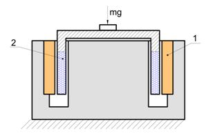
Fig. 4.1. Functional diagram measuring system of mass with electromagnetic servo-motor; 1 – permanent magnet, 2 – the coil hanging on the system of beam - not visible in the picture.
The above described electromagnetic system has several disadvantages:
- complicated and precise mechanical design,
- complicated transmission ratio of the beam and necessity of applying of compensation system when the measuring force is not put in the centre of the pan;
- big owner mass as a result of big mass permanent magnet Fig. 4.1;
- small resistance to external electromagnetic fields;
- significant consumption of electric power (current iin the equation (2) and heat emitted from the coil which change temperature inside the electronic scale);
- small resistance to vibration, acceleration and mechanical over load.
Disadvantages of electromagnetic system cause research new solutions in the field transmitters of mass. About 1960 there was created a new solution: strain gauge load cell based on the physical elastic properties of the beam, made generally from aluminum alloy or sometimes from stainless steel Fig. 4.2.
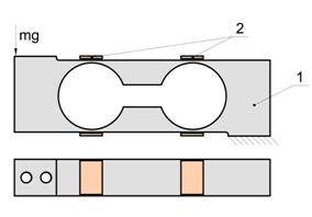
Fig. 4.2. Strain gauge load cell; 1 – body of the beam; 2 – strain gauges.
Four strain gauges are bonded in the places of the smallest cross sections and they change resistance as a result of putting outside force mg. This strain gauge is connected with Wheatstone bridge whose output tension is proportional to measuring mass m.
(3)
where: U – output tension of Wheatstonne bridge, ![]() – proportional coefficient, m – measuring mass.
– proportional coefficient, m – measuring mass.
The above described solution introduces significant development in the field of measuring mass; it is simple and more reliable than the system with electromagnetic servo-motor, (Fig.4.1), in this system we can measure big mass with small consumption of electric power.
Strain gauge load cells are commonly used in the field of measuring mass especially in design of electronic scales with wider ranges than 2 kg and resolution of 3000.
But strain gauge load cells fig. 4-2 has also a lot of disadvantages:
- small resistance to the vertical and lateral load forces (150%);
- measuring range above 2 kg (sometimes there are designed electronic scales with ranges lower than 2 kg, but it has smaller accuracy and doesn`t meet PN EN 45501 standards).
- limited measuring accuracy (generally the scales III class of accuracy);
- difficulty technological process bonding of strain;
- it is necessary to compensate changes of Young module of aluminum alloy beam as a temperature function;
In spite of these disadvantages strain gauge load cells and the system fig. 4-1 are commonly used in electronic scales and other measuring systems.
3.Inductive measuring load cell
A new design of inductive measuring load cell is based on anther phenomena than the one described above. It has been resigned from strain gauges, which are generally used to measure local strain on the metalic surface - it was applied as a well known in another field of metrology - inductive sensor of displacement Fig. 4.3.
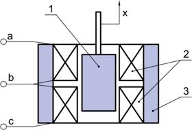
Fig. 4.3. Displacement inductive sensor, 1 – ferrite core, 2 – coils, 3 - ferrite pot, a, b, c – output from coils.
It consists of two coils 2, the moving core 1, the ferrite pot 3, which conducts the magnetic flux, generated by electric current in the coils. This sensor works in the differential mode, which means that in symmetrical position of the ferrite core, the voltage U Fig. 4.4 equals zero. Displacement of the core 1 from the steady state, causes the change of voltage U Fig. 4.4 which is proportional to this displacement.
The below described inductive sensor of displacement was applied in the design of inductive measuring load cell Fig. 4.5. The moving part of the beam is connected with the pan of the scale, on which we put measuring mass. As a result of putting this mass, appeared a small displacement of the flat springs and moving of ferrite core of inductive sensor. The core of sensor is connected with moving part of the beam but the body of sensor is also connected with the basis a inductive load cell.
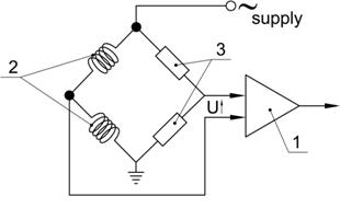
Fig. 4.4. The measuring bridge of displacement inductive sensor, 1 – amplifier of a/c current, 2 – coils, 3 – resistors, U – output voltage of the bridge.
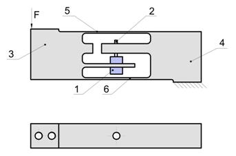
Fig. 4.5. Inductive measuring load cell, 1 – inductive sensor of displacement, 2 – core of sensor, 3 – moving part of the beam, 4 – basic part of the beam, 5, 6 – measuring springs.
Measuring elements of inductive load cell are two flat springs parallel to each other. They are fastened at one end to the motionless part of the beam and at the other end to the moving part of the beam. The above described connections is solid and stable because the springs are made of the same material as other parts of the beam.
4. Comparison strain gauge load cell with inductive load cell
Between strain gauge load cell Fig. 4.6b and inductive load cell there are the following differences:
- The measure of displacement using inductive load cell is touch less – the spring of the measuring system is not loaded by strain gauges and glue.
- The inductive sensor measures total displacement at the end of the beam but the strain gauge measures stresses in a few places of the measuring beam. In the strain gauge load cell, technological process production requires accumulation of strains in the places of gluing of the strains. The segment of the beam Fig. 4.6, in which there is maximum strain must be shorter than length of strain gauge. Local stress concentration draws its value maximum stress in using material. It causes higher hysteresis and more creep of material under constant load.
- The core of the sensor can move without restriction even above 1 mm, than in the electronic scales with small ranges, there is possible ten times overload. It is very important in industrial application.
- Inductive measuring load cell can be designed for small measuring ranges for example 0 – 30g which are impossible to achieve using strange gauge load cells. Here it is possible to design electronic scales II class which at present we can make only using electromagnetic servo-motor.
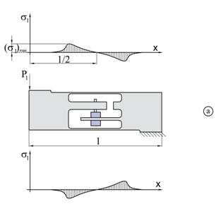
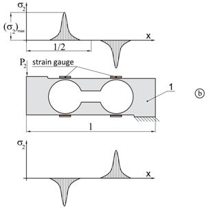
Fig. 4.6. Tension distribution of inductive load cell “a” and strain gauge load cell “b”.
Inductive method for measure of mass has not any restriction to high measuring ranges of mass for example several tons. The principle of this method - measuring total displacement of the beam, permits achieving easier design of transmitter than when using strain gauge and measuring local stresses.
- Accuracy of inductive load cell is higher than that of strange gauge load cell as a result of tension distribution in both cells fig. 4-4. Less tension in the measuring spring of inductive load cell cause less hysteresis, less creep of material under constant load and better linearity of static characteristics.
To assume that both cells, inductive and strange gauge are loaded with the same forces ![]() and
and ![]() Fig. 4.6.
Fig. 4.6.
where:
where:
load cell
From Castigilana theorem which define inside elasticity energy V both cells created as a result of putting outside forces ![]() and
and ![]() we have:
we have:
(4)
From the above equations we can see that inside elasticity energy of both systems are the same, it means that area under curves is te same:
(5)
thus, taking into account the character of curves ![]() and
and ![]() the maximal stresses in
the strain gauge beam
the maximal stresses in
the strain gauge beam  are considerably greater than the maximal stresses in the
inductive beam
are considerably greater than the maximal stresses in the
inductive beam under the assumption of equal external conditions and the same
material from which both beams are fabricated
under the assumption of equal external conditions and the same
material from which both beams are fabricated
(6)
Thus, making two beams; a strain gauge beam and one inductive, from the same material, the
hysteresis errors and material flow will be smaller in the first one.
Calculation of the static characteristics of the inductive beam is relatively simple, the deflection ![]() can be determined from the equation well-known in strength of materials science:
can be determined from the equation well-known in strength of materials science:
(7)
where: l – length of spring,![]() – the force, b – wide of spring, h – thickness of spring, E – Young module.
– the force, b – wide of spring, h – thickness of spring, E – Young module.
5. Digital correction of the mechanical errors of the beam
The main research works in the field of inductive beam concern an increase in its metrological parameters using mechanical and technological methods it means: looking for optimal geometry, applying good materials, suitable technological process production etc. Mechanical assemble which has good metrological parameters is more reliability and cheaper than similar elements in electronic system.
Improvement of metrological parameters of inductive beam in the mechanical way has some restrictions and in the end it is necessary to use digital correction. The real output signal of inductive load beam is going to the processor’s memory and this signal is modified according to suitable mathematical equation. The design of the algorithm of the errors correction and finding suitable mathematical equation is the first step of programming process.
Before we start to describe the above mentioned digital correction method, it is necessary to analyze physical phenomena which causes those errors.
5.1. Hysteresis
The main problem of inductive measuring method of mass is hysteresis. The value of this hysteresis in aluminum alloy is very small and equals 3 to 5 graduations for resolution 30 000. The results hysteresis research for the beam with the range of 15 kg is shown on Fig. 4.7 (in these tests measuring electronic system resolution of 100 000 was used).
m [kg] |
indication |
indication [kg] |
0,05 |
0,0495 |
0,0500 |
0,5 |
0,4995 |
0,5005 |
2 |
1,9995 |
2,0010 |
5 |
4,9995 |
5,0010 |
10 |
10,0000 |
10,0005 |
15 |
14,9990 |
14,9990 |
Fig. 4.7. The results of the test of hysteresis of the inductive load beam.
The table in Fig. 4.7 shows the value of mass m as the load of beam in the function of indication module of scale for increasing and decreasing value of m:
where: m – the mass loading the beam, w – indication of display.
(8)
where: m – the mass loading the beam, w – indication of display.
We can show the above described results of test as the diagram Fig. 4.8 where on the ordinate there is difference between theoretical straight line with the slope ![]() . This line connects zero of coordinate system with ¾ distance point from that zero, Fig. 4.8.
. This line connects zero of coordinate system with ¾ distance point from that zero, Fig. 4.8.
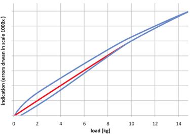
Fig. 4.8. Diagram of hysteresis of inductive load cell with range 0-15 kg
In the Fig. 4.8 on the axis of ordinate there is 1000 multiply magnification because the value of hysteresis errors is very small. In this way in the picture Fig. 4.8 we can see typical hysteresis loop. Small hysteresis errors of aluminum alloy is a good quality for measuring system of mass.
The point ¾Max on the x axis is chosen because in that point there is the best linearity of the characteristics inductive load cell shown in picture Fig. 4.8. At the maximum point of these characteristics it is curving, which causes non linearity characteristics of inductive sensor of displacement.
The value of hysteresis inductive load cell depends on two parameters:
- the geometry measuring springs;
- kind of material of inductive load cell.
According to chapter 4.1 small hysteresis has the beams with flat measuring spring. But also the spring which has holes, Fig. 4.9 could achieve satisfactory accuracy for III class of electronic scales.
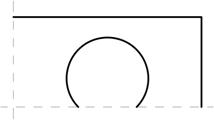
Fig. 4.9. Circular shape of measuring springs.
Technological process, Fig. 4.9 is obviously easier than technological process of the flat spring shown in Fig. 4.5. In spite of, the same shape of inductive load cell and strange gauge load cell, the principles of work of the both beams are different. In the case of strange gauge load cell we measure the strange on the surface but in inductive load cell we measure the whole displacement at the end of the beam.
The value of the above described hysteresis depends also on kind of machining used during the production of the beam. During the machining of the beam, is produced a heat which changes structural crystallography laver of the material near the cutting tool - as a results of this physical phenomenon, elasticity properties of the beam are worse.
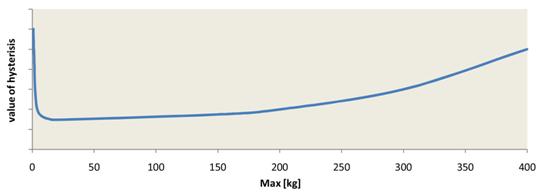
Fig. 4.10. Value of hysteresis of inductive load cells as the function measuring ranges - as a result machining of the beam and the value of the strange in the material of the springs.
The total effect of the above described physical phenomenon is bigger when the measuring spring is thinner, because damage of material in this case is bigger. On the other hand in the thin springs there are less strains. The above described effect of physical phenomena causes that in practice less value of hysteresis of inductive load cells is for ranges about 200g to 15 kg, Fig. 4.10
5.2. Creep material of the beam under constant load
Creeping of material under constant load is commonly known in the field of strength of materials – it also concerns the inductive load cell. Similarly as in hysteresis, slow increase of displacement at the end of the beam loaded by constant force depends on the following parameters:
- kind of material;
- geometry of the beam.
The characteristic deflection of the beam under constant load as a function of time is shown in the picture Fig. 4.11 – red curve.
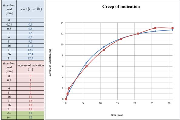
Fig. 4.11. The characteristic inductive load cell under constant load m=15kg.
As we can see in the picture Fig. 4.11 during the first minutes after putting the load deflection of the beam is fast – next this deflection is changing slowly according to the exponential curve:
where: y – deflection of the beam, A and b – coefficients, t – time.
(9)
Experimental curve (red colour) is shown in Fig. 4.11 and simultaneously there is a theoretical curve (blue colour) according to the last equation. Selecting coefficients Aand b we achieve the same shape of both curves.
Sometimes, we achieve a better approximation of the creep material characteristic, using two units of exponential curve, because at the beginning when we load the beam of mass its deflection is rather fast and next it goes as asymptotic to constant value.
where: y – deflection of beam, t – time,
(10)
The coefficients ![]() are determined by experiment. In this way there is corrected physical phenomena creep of the material of inductive load cell.
are determined by experiment. In this way there is corrected physical phenomena creep of the material of inductive load cell.
Physical phenomena of hysteresis and creep of material are closely connected; a hysteresis loop Fig. 4.8 is created by creep of material in all measuring points. As a result, the value of indication of mass on low part of that curve is smaller than similar value of indication on a theoretical straight line.
6. Influence of ambient temperature
The change in ambient temperature causes change of Young module aluminum alloy of inductive load cell. It causes change of the slope of the statistic characteristic ( change of amplifier gain) and displacement of initial point of work. Equation of this characteristic as a equation of straight line in coordinate system (m, w) is:
(11)
where: w – indication of measuring system, m – weighing mass, a, c – coefficients.
where: T – ambient temperatures.
The coefficient m determined measuring system gain and the coefficient c describes displacement of that characteristic on the plane (m, w).
In the Fig. 4.2 there are two static characteristics: 1 – before temperature compensation (red), made after mounted of the scale and 2 (blue) – after temperature compensation as well after changing of the coefficient gain a and with changing the coefficient c compensating displacement of initial point of work.
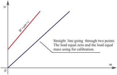
Fig. 4.2. Influence of ambient temperature on static characteristics of inductive transmitter.
Temperature compensation is made by drawing a straight line 2 through two points: for load equal zero and load equal calibration of mass Fig. 4.2. During normal work the ambient temperature is measured using a temperature sensor with resolution 1/4°C; change of Young module of inductive load cell is corrected by a microcontroller. Inside the body of the beam there is a temperature sensor, in this way we have the same dynamic in temperature measuring system both in the sensor and the beam.
7. Summary
Minimize above described errors of inductive load cell is made in two stages.
- the first stage concerns the design and technological works which are leading parallely with production process, for example: minimizing physical phenomena like: hysteresis and creep of material. They can be achieved using a good material for inductive beam and applying a good heat treatment.
- the second stage concerns correction of mechanical errors of the beam, applying suitable program of microcontroller
The first method is the best one because we achieve high reliability, this method is sufficient for the electronic scales of III class. In the case of II class of electronic scales it is necessary to apply digital compensation of above described errors, especially to minimize physical phenomena like: hysteresis, creep of material under constant load and correction nonlinearity static characteristics.
The same principle of design of all inductive load cells for different measuring ranges permit applying one type of microcontrollers to all types electronic scales. It is possible because the errors: hysteresis, creep of material, nonlinearity of static characteristic , the influence of ambient temperature and humidity on all measuring ranges of mass is the same.
The above described errors are similar because all inductive load cells are made from the same material, they have the same inductive sensor of displacement. A work with the same displacement which equals 0,2 mm. As a result of this influence the change of ambient temperature on Young module is the same in all types of inductive load cells.
The results of the research were applied by MENSOR company in production process of inductive load cells and in the design of electronic scales which earned Certificate of EC Type Approval NO PL 06 003 issued by The Main Measuring Office in Warsaw.
References
- M. Jafaripanach, B.M. Al.-Hashimi, N.M. White: “Load Cell Response Correction using Analog Adaptive Techniques”. IEEE International Symposium on Circuits and Systems, Bangkok, Tailand, 2003, pp. IV752-IV755.
- M. Jafaripanach, B.M. Al.-Hashimi, N.M. White: “Dynamic Sensor Compensation Using Analogue Adaptive Filter Compatible with Digital Technology”. Accepted for publication in IEE Proc. Circuits, Devices & Systems.
- J. Lewandowski: Measuring Transmitter of Electronic Scales. Patent, no. PL 175320 B1.
- J. Lewandowski: “Computing Measuring System of Mass and Non-electric Physical Parameters”. Proceedings of the 3th International Seminar in Precision and Electronic Technology, INSEL 2007, Warsaw 19-20 Nov., vol. 3, 2007, pp. 187-190.
- J. Lewandowski: “Inductive Method for Measure of Mass”. PAR, no. 5, 2000. (in Polish)
- J. Lewandowski: “Inductive Sensors of Force”. Proceedings of the 4th International Seminar in Precision and Electronic Technology, INSEL 99, Warsaw 22-24 Nov., vol. 4,1999, pp. 225-231.
- TECH NOT Measurements Group – Fatigue Characteristics of Micro-Measurements Strain Gages, Measurements Group, Inc, P.O. Box 27777, Raleigh, North Carolina, USA.
- TECH NOT Measurements Group – Noise Control in Gage Measurements, Measurements Group, Inc, P.O. Box 27777, Raleigh, North Carolina, USA.
- TECH NOT Measurements Group – Errors Due to Transverse Sensitivity in Strain Gages, Measurements Group, Inc, P.O. Box 27777, Raleigh, North Carolina, USA.
Contents
![]() About MENSOR company
About MENSOR company
![]() New inductive method for measure of mass
New inductive method for measure of mass
![]() Medical scales
Medical scales
![]() Scales for weighing animals - Veterinary scales
Scales for weighing animals - Veterinary scales
![]() Electronic Platform and Storage Scales
Electronic Platform and Storage Scales
![]() Electronic table scales
Electronic table scales
![]() Electronic scales and parts counting systems
Electronic scales and parts counting systems
![]() Hook electronic scales
Hook electronic scales
![]() Electronic Precision Scales
Electronic Precision Scales
![]() Electronic Laboratory Scales
Electronic Laboratory Scales
![]() Electronic scales for production automation
Electronic scales for production automation
![]() Indication and dosing systems
Indication and dosing systems
![]() Weighing Modules
Weighing Modules